The tiles edition is divided into five parts:
| View | |
| Tile Selection | |
| Tile Size | |
| Tile Overlaps | |
| Tile Crop Marks |
Good to know
In the case of the size of the tiles, as well as the dimensions of overlaps, white areas, and gaps, the values displayed reflect the selection, whether it consists of one or several tiles.
Also, an empty field does not prevent you from entering a value. If you enter a value in an empty field, the value will be applied to all selected tiles.
Caution
If the selected tiles have different values, these values won’t be displayed at all.
View
This option is used to customize the display of the poster.
The first cursor adjusts the display of the foreground and background images:
- If the cursor is placed completely on the left, only the main image will be visible
- On the contrary, if the cursor is placed completely on the right, only the background image will be visible.
- Examples of the cursor placed to the left, middle, and right:
The second cursor adjusts the display of the image and the overlap, gaps, and white marks. In the previous example, the “image” corresponds to the combination of the foreground and the background images as decided with the cursor.
- If the cursor is placed completely on the left, only the image on the poster will be visible.
- On the contrary, if the cursor is placed completely on the right, the image will be hidden, but the overlap, white, and gap marks will be visible.
- Examples of the cursor placed to the left, middle, and right:
Good to know
By default, the cursors are placed in the middle. This way, both the image and the overlaps are visible.
A click on the button at the end of the line moves the cursor nearer to it by stopping in the middle if it is closer to the other part of the line.
Tile Selection
This area gives you access to a dynamic tile selector. The selection options are::
- All
- Row (named Row 1, Row 2, etc., from top to bottom)
- Column (named Column 1, Column 2, etc., from left to right of the poster)
- Select a tile individually (click here to see more info about tile names/labels)
It is also possible to select tiles directly in the Preview. If you selected tiles from several levels (different rows or columns), the “Multiple” label is displayed in the Selection field like in our example.
The numbers displayed right next to the Selection menu are the number of tiles selected concerning the total number of tiles. In our example, 6 tiles have been selected for a total of 15 tiles.
Tile Size
This area of the window displays the values of the whole selection of tiles.
When selecting one or more tiles, two details will be displayed under the Tile Size text:
- The external size of the selected tiles, taking the overlap into account.
Info
Only identical sizes are displayed, which means that if the height is not identical, only the width will be shown. If both height and width are different for the selected tiles, “multiple values” are displayed instead of the external size.
- The selected tiles' location. In our example, only a tile has been selected and it’s the L1C4 tile.
If a row or elements from the same row are selected, this will be indicated alone. The same principle applies to the columns. If elements are from different columns and rows, the location won't be displayed.
Caution
If the selected tiles have different values, these values won’t be displayed at all.
Also, an empty field does not prevent you from entering a value. If you enter a value in an empty field, the value will be applied to all selected tiles.
Internal dimensions
Internal Width and Height correspond to the tile itself, without overlaps, as seen on the poster Preview.
If the selected tiles have different sizes, the different fields will be empty. You can put a value in it and it will be applied to the selected tiles.
Locking dimensions
The two lock-shaped icons next to each field allow you to lock the tiles to prevent their size from being modified. If the tiles are locked, then you cannot resize them directly or indirectly (resizing a tile by moving another file, for instance).
You can also lock multiple sessions. The locks can be set tile by tile: in the same poster, you can therefore define the first tile as being only vertically editable, the second tile as being only horizontally editable, and so on.
The tiles that have at least one component locked appear in pink on the Preview when they are not selected:
When the dimensions of a selection are changed, and it impacts locked tiles, the following pop-up will be displayed to inform you that only unlocked tiles will be modified.
Caution
Be careful, if the changes have to be done on the width while the tile is locked on the width, the column will not change.
You also can lock a tile width and/or height by making a right-click on it and selecting the corresponding action on the list:
Merge, Split, or Disable
These buttons allow you, once the tiles are selected, to split, merge, or disable them.
This button allows you to merge tiles. These must be side by side and their merge has to have a rectangle shape and not an odd non-regular one. You also must select at least 2 tiles to activate the button. Check the following before/after:
This button allows you to split the selected tile (it must be a merge of several tiles). The division completes the grid that is created by the tiles. Below, you can see before and after the tile split and how the division completed effectively the grid:
This button allows you to horizontally split one or several tiles in two. Following, there is an example of a tile split several times. When you split a tile, you automatically select the two tiles you’ve just created. If you redo the split, you see four tiles and so on:
This button allows you to vertically split one or several tiles in two. Bellow there is an example of a tile split several times. When you split a tile, you automatically select the two tiles you’ve just created. If you redo the split, you see four tiles and so on.
Disable the selected tiles. These tiles will not be generated during the poster-creating process, which also means that these will not be printed.
A click on this button activates or disables the selected tile. Note that if none is selected, then all will be disabled until you click back on the button. The disabled tiles appear with a red cross on the Preview, as you can see next:
If you make a right-click on one or several tiles, you can see and do the merge, split, or disable actions on the selected tiles:
Tile Overlaps
Caution
If the selected tiles have different values, these values won’t be displayed at all.
Also, an empty field does not prevent you from entering a value. If you enter a value in an empty field, the value will be applied to all selected tiles.
The overlaps are useful to avoid the appearance of white areas when joining the different tiles that make up your posters or to facilitate the assembly or pasting of the tiles (as certain types of glues can dissolve the inks, thus losing effectiveness).
This part of the module allows you to define tile overlaps, but also to include a white area if necessary, or to leave a space between tiles.
Caution
Changes made in this section are applied to the selected tiles only, so tiles can have different gap or overlap values.
The Tile Overlap table is the only element you can see when you minimize the section (using the corresponding icon).
This table tells you, for each selected tile, which gap, overlap, and white area will be applied, as well as the type of line used to show it in the poster printout.
The table is for information only, so you cannot modify the values directly in it.
Edit
These icons are used to specify the side of the tile on which the values of the input fields located below will be applied. Activated borders are highlighted in orange. To activate or deactivate a border, just click on the icon.
In this sense, if you want all sides to contain the overlaps, like in the example before, then you must activate all icons.
Saving the gaps/overlaps/white
There are default values for the overlaps, the gaps, and the white (0). However, these values can be manually modified. Once you do so, just click on the Disk icon next to the Edit area. The changes done will become the new default values (and will remain there even if you restart CalderaRIP).
Caution
If the “mult” label appears in one of the fields of the upper table, it means that the selected tiles have different overlaps, gaps, or white dimensions. In this case, clicking the Disk icon will not save the values (as this function can only record unique values).
Gap
Here you can define if spaces between the tiles of the poster must be placed. The unit is the one you have chosen for the module. The value will automatically be recalculated if you change the unit.
This is particularly useful if you want to hang your tiles on panels that are not very close to each other, for instance (notably in the case of a metal bar between two panels). In this case, the Gap function will delete a small part of the image between each tile (this part corresponds to the width of the bar), so that your image, once hung up and seen from a certain distance, keeps all its visual coherence.
A gap can be created on a tile or centered on two tiles. In this case, for example, you will have to select the Left and Right icons, or the Top and Bottom icons, in the Edit part of the Tile Overlaps area, and apply half the gap on each side.
Info
If you define a gap between two tiles, there is usually no need to apply overlaps, since the gap is above all meant to create a hole between certain parts of the stand support (for instance, poles between panels). Nevertheless, such configuration is possible.
Overlap and White
In general, you would want an overlay that leaves a thin band of the image showing, as the goal is to make it easier to lay and prevent white areas from appearing, followed by a large uninked portion (this will be used to apply glue or solder).
In this sense, you may not usually choose to apply an overlap or white on all four sides of a tile. However, it is possible to do so. Your overlaps will be set depending on the direction in which you want to glue your tiles.
If you want to glue your poster from left to right and bottom to top, you will need to set overlaps and/or white areas on the bottom and right sides of the tiles.
On the contrary, if you want to glue your sign left to right and top to bottom, you will need to set overlaps on the bottom and right sides of the tiles.
Info
Please note that by using Tiling+, you can create posters that can be glued in any direction.
Once the tile is printed, it will contain part of its adjacent tiles, corresponding to the overlaps. This is the reason why the size at the time of printing is always larger than the size of the tiles as defined.
Alternative Overlaps
If the Alternative Overlaps option is activated, adjacent tiles will then have the same overlap on both sides of their common edge, and the line will be drawn at a place different from the regular one.
Line
The Line option allows you to define how the overlap or white part will be indicated on the poster.
Info
The blue and red marks showing overlap and white in the Preview do not appear on the poster. To get visible marks on the poster, you need to define a line.
Click the […] button to edit the line settings.
First, choose the line Type that will be used:
- None: No line
- Plain: Solid line
- Dashed: Dotted line
- Edges: Only the beginning and the end of each line will be printed
- External: Like Edges, except that only the part outside of the image is printed in the crop marks area
Then define the line Thickness:
- Either check the 1-pixel box, the line will automatically be 1-pixel thick
- Or enter directly the value in the field (If 1 pixel is activated, you will have to uncheck it first)
Info
Values are expressed in the measuring unit selected at the bottom of the window, i.e. inches or millimeters.
Finally, choose the color. Double-click on the colored area to open the color selector.
- You can choose your color in the following color spaces: LAB, XYZ, or HSB on the left or RGB, CMYK, or GREY on the right.
- Enter the value or pick it with the pipette then click on OK to validate it.
The line of the overlap shows the limit between the image on the tile and the overlap containing a part of the adjacent tile. The line of the white shows the limit between the overlap and the white area.
Example of a tile (the black frame) after the poster creation:
Preview
On the poster Preview, overlaps will appear by default in red and white areas in blue. Both are represented outside of the tiles since they correspond to parts of the picture located on contiguous tiles.
Info
Likely, overlaps or white areas will not appear at the edges of the poster in the Preview, even though they appear in the summary. This is normal since there is nothing to print on an edge The only usefulness of these values is to make the global edition of the overlaps easier.
The lines do not appear on the Preview either, but they will be printed on tiles.
Tile Crop Marks
In this area, you can choose the type of Crop Marks as well as the information you want to see printed on each of your tiles.
Info
Contrary to the other sections, this one’s changes are made on all tiles and not only the selected ones.
Crop marks
This section displays the various types of marks available. As you may notice, these marks are the same ones present in the Print module.
You can activate or deactivate one by clicking on it. When they are orange, it means that they are activated. You can apply one, several, or none at all.
Crop marks meaning:
Standard: Standard marks are placed on each corner of the tile
Frame: Draw a continuous frame around each tile
Corner: Marks are placed on each corner of the tile (these marks are not the standards)
Target: Targets are placed at mid-height and mid-width of the page (cross shape)
The three fields below are linked to these elements:
- Margin: Distance between the printed part of the tile and the mark
- Size: Length of the line used for the mark
- Thickness: The thickness of the line used for the mark
Frame
This is a line drawn around each tile, which signals the separation between the tile and the crop marks. Click the […] button to edit the frame settings:
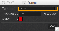
First, choose the line Type that will be used:
- None: No frame
- Plain: Solid line
- Dashed: Dotted line
- Edges: Only the beginning and the end of each line will be printed
- External: Like Edges, except that only the part outside of the image is printed in the crop marks area
Then define the line thickness:
- Either check the 1-pixel box, the line will automatically be 1-pixel thick
- Or enter directly the value in the field (If 1 pixel is activated, you will have to uncheck it first)
Info
Values are expressed in the measuring unit selected at the bottom of the window, i.e. inches or millimeters.
Finally, choose the color. Double-click on the colored area to open the color selector.
- You can choose your color in the following color spaces: LAB, XYZ, or HSB on the left or RGB, CMYK, or GREY on the right.
- Enter the value or pick it with the pipette then click on OK to validate it.
Additional information
(Checkboxes at the end of the Tile Crop Marks area)
Other kinds of information can be added to your tiles before these are printed. The information will be placed out of the tile, in the crop marks margin.
- Date: Adds the poster creation date (not the printing one). The date will be added at the right-top of the image
-
Tile Name: Adds the tile name.
Info
CalderaRIP Version 17 or later: By default, now the label format is %n_L%rC%c (Poster_L1C1, Poster_L1C2, etc.).
The new default label format will apply only to new installations or when the last configuration has been deleted.CalderaRIP V16.3 or later: Since this version, now the name of the generated tiles matches the label pattern (in other words, tile labels and names became the same).
The previous caused a collateral effect, as now the labels/names do not fit when trying to nest a tile project. We are working to correct this behavior.CalderaRIP Version 16.3 or before: By default, the label format is L%rC%c (L1C1, L1C2, etc.).
If you have any problems with tile names or labels, feel free to visit this support article.
- Cutting Frame: Places a frame around your tiles in case these have to be cut by a cutting peripheral using Caldera RIP’s Print-to-Cut workflow. The contour’s name is: “CutContourFrame”.
-
White Crop Margins: In the Print Module, the crop mark margins are always white. In the Tiling+ module, part of the image may appear in the crop mark margins if you need to. Therefore, if this option is not activated, the picture will appear behind the crop marks. On the contrary, if activated, the margin will be white.
Info
If the cutting is not very accurate, the previous may prevent the apparition of white areas.