The following features, which were previously included in the legacy VisualCut and GrandCut options, are now included in annual CalderaRIP subscriptions and perpetual licenses with CalderaCare.
Partners and resellers should consult the Partners Portal for details; end-users can find information on our website.
The Cutter Tools Configuration allows you to manage advanced features for marks, margins, materials, and methods when working with supported cutters.
How to access the Cutter Tools Configuration?
- Open CalderaRIP.
- Open the Print Module of any of your printers. Click on Page setup.
- Go to the Cutting tab.
- If you haven't already, click on Enable Cutting Contour.
- Click on Tools.
- A pop-up will open with the Cutter tools configuration:
|
|
You might also want to read:
Cutter Tools Configuration window
Good to know
The fields in the Cutter Tools Settings window depend on the physical capabilities of the selected cutter model. This article covers some common options, but if you need specific information, please refer to the technote for your cutter or contact the manufacturer.
Warning
The values you enter in the Cutter Tools Settings window (such as margins and mark positions) are linked to your printer preset (also known as QuickPrint), not the cutter itself.
Changing the cutter will reset these settings, but you can retrieve them by reloading the previously saved preset configuration. Additionally, a cutter tool configuration set with one cutter cannot be accessed in another printer module, even if the same cutter is selected.
The Marks and margins tab is divided into 5 main areas: Custom margins, Positions, Cutter limits, Misc, and Sorting.
Custom margins
When "Use custom margins" is enabled, the options are divided into: Margins, Marks offset, and Marks placement.
Info
You can always click on the Default margins button to reset the margins to the default values.
The following two buttons allow you to...
-
 Save your cutter configuration
-
 Launch a saved configuration
Margins
You can set Left, Top, Right, and Bottom margins.
Marks offset
Allows you to define the space around the image that will contain the cutting marks. With GrandCut devices, the marks will be placed inside the image if you define the Left, Top, Right, and Bottom margins at 0.
Here you can set the margins between the frame created by the Marks offset and the roll or page border. You can set Left, Top, Right, and Bottom margins.
In the second example, the Marks offset equals 0 and the marks are placed on the image.
Marks placement
You can set the Horizontal/Vertical Spacing between the marks when available.
Info
The Horizontal/Vertical Size and Thickness are fields dedicated to VisualCut cutters.
Positions
It allows you to set the positions of Edge Marks and Barcodes:
Position of the edge marks and others
The Edge Marks parameters allow you to select on which side of the job these marks will be added (when the icon is orange, it means that the side is selected):
 |
 |
 |
 |
| Top | Bottom | Left | Right |
Disable extra mark at origin: For some cutters, an extra mark is added at the bottom right corner by default as they use it to detect job orientation. Use "Disable extra mark at the origin" if you do not want this extra mark (especially useful for mirroring jobs).
Force rotation (Only available for a defined list of cutters). This setting forces the rotation to one of the following angles:
- Auto: Normal or auto rotation to fit cutter width.
- 0 degrees: No rotation is applied.
- 90 degrees: Rotates the cut jobs by 90° degrees, when the origin and the front of the cut table are rotated 90 degrees.
- 180 degrees: Rotates the cut jobs by 180° to match rolling/unrolling 2-step workflows (like sublimation or lamination).
- 270 degrees: Rotates cutting jobs 270° degrees (90° counterclockwise) when the origin and the front of the cutting table are rotated 90° counterclockwise.
Auto-rotate job to fit cutter width: This option works with the Cutter limits (and especially with the Width). This option can be useful when the print width is too large to fit in the cutter and needs to be rotated.
Example: If you have a 60×30 job printed on a 64” roll and your cutter is only 36” wide, you can rotate the job for the cut so mark placement needs rotation too.
Barcodes
The Following settings apply to Barcodes and QR Codes. The side icons are the same as described in the previous section for Edge Marks. Similarly, when the icon is orange, it means that it is selected:
|
|
Side activated |
Side deactivated |
These three settings are linked to the Side activation:
-
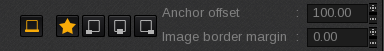
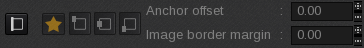
Mark placement: for each side, you have four choices for where to position the barcode:
-
 Auto: CalderaRIP will place the barcode automatically (legacy behavior)
 -
 First border: Left or Up depending on the side
 -
 Center.
-
 Second border: Right or Down depending on the side
-
- Anchor offset (only available if Auto is not chosen). This parameter allows you to move the barcode to adjust its placement. The Anchor offset makes the barcode move to the center. A positive offset moves it clockwise for an already centered barcode, while a negative offset moves it counterclockwise.
- Image border margin (only available if Auto is not chosen). This defines the spacing between the image and the barcode.
Finally, you can find the Barcode and the ID number sizes.
Cutter limits

Here you can set the Width and Height of the cutter. These parameters work with the Auto rotate job to fit cutter width setting.
If the job is too wide, the job will rotate. If the height has been set, a check will be made to see if the rotated job can fit. If not, CalderaRIP will undo the rotation.
Caution
Beware, the software won't display a warning if the job does not fit within the physical limits of the cutter.
Misc

These settings allow you to Generate segments rather than Bezier curves and also to choose the Marks type (between Cross or Dot).
As of CalderaRIP V17.3, A new "Add direction mark" checkbox was added to the Misc. area for almost all cutting drivers (both GrandCut and VisualCut):
|
|
|
Activating this new field adds direction marks in the form of a triangle pointing to the bottom edge of the cut job, which significantly speeds up the operators' work when managing these files.
Other settings might be available depending on your cutter model.
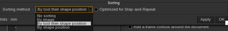
Sorting
Info
The Sorting area elements are only for cutters driven by GrandCut.
The Sorting method will choose the optimized path to select the next contour to be cut to save time. This lets the user specify the cut order: by image, cut tool, or shape.
Tips & tricks
If you want to see directly an example of all the above configurations, click here.
Depending on the GrandCut you are using, you might have two additional tabs: Materials and Methods.
Info
Some cutters/drivers require you to enable the Use methods/materials option (located in the Marks and margins tab, in the lower Misc area).
Methods tab
In this tab, it is possible to associate the cut contours existing in your job with a specific cutting method (correlation of 1:1).
Tips & tricks
You can use wildcards to associate several contours to the same tool/method (name*, *name, or name). You can also "populate" methods filters: read more about it in this article.
Materials tab
In this tab, it is possible to associate the media (substrate) from your printer with a specific material (correlation of 1:1).
Info
Once changes are made, you must close and reopen the window to refresh other tabs, such as Methods (contours - methods associations) and Materials (printed media - materials associations).
Starting with CalderaRIP V18, this tab also includes a "Smart Materials" button. Learn more in the dedicated article.
Info
The "Editor tab" is a GrandCut feature included in CalderaRIP starting from Version 16.0. It was designed for devices that do not support automatic synchronization of materials/methods, which currently are the following:
|
|
|
The GrandCut Editor allows you to synchronize methods and materials, a task that was previously done manually by editing the XML cutting files directly. Learn more about the methods/materials association with the following dedicated articles:
- How to manually associate materials and methods between CalderaRIP and the controller?
- How to automatically associate materials/methods with the GrandCut Editor?
Once you are in the editor tab, you will see two columns: one for creating, deleting, or editing materials, and the other for creating, deleting, or editing the methods that will be associated with the materials.
Info
The information contained in the editor is related to the information contained in the other tabs Methods and Materials.
Once changes are made, you must close and reopen the window to refresh other tabs, such as Methods (contours - methods associations) and Materials (printed media - materials associations).